
Planning for Pressure, Not Problems
A well-designed compressed air system is a thing of beauty, delivering consistent pressure and ample airflow to every corner of your shop. A poorly designed system, however, can be a source of constant frustration, with tools starving for air and a compressor that seems to run nonstop. The key to success lies in proper planning and understanding how to size your system for your specific needs. Let’s answer some critical questions about system design and pipe sizing.
How do I figure out what diameter pipe I should use?
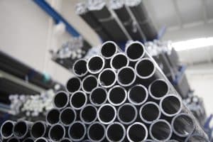
This is one of the most common and important questions in system design. The right pipe diameter depends on two main factors: the total airflow your tools require (measured in Cubic Feet per Minute, or CFM) and the total length of your pipe run. A smaller pipe might be cheaper, but it will cause more friction and a greater pressure drop over a long distance, especially at high flow rates. As a general rule, a small garage workshop can often get by with 3/4″ pipe, while larger shops or those with high-demand tools (like a dual-piston sander or large media blaster) will benefit significantly from 1″ or larger main lines. The goal is to minimize pressure drop, ensuring the tool at the end of the line has nearly the same pressure as the air leaving the compressor. Using a larger main line and then stepping down to smaller pipe for the individual drops is a very effective strategy.
I’ve heard about “looped” systems. Is that better than a simple straight line?
For larger or more demanding workshops, a looped system is the gold standard of compressed air design. Instead of having a single line that dead-ends at the farthest point, a looped system forms a complete circle or rectangle around the perimeter of the shop. Air can then travel in both directions from the compressor to any point of use. This simple change has a massive impact. It effectively doubles the pathways for air to travel, which dramatically reduces pressure drop and ensures that even if one user is drawing a large amount of air, other users on the loop will still have plenty of pressure. It provides system-wide stability and is the most efficient way to deliver air in a busy environment with multiple users.
What is pressure drop and how do I minimize it?
Pressure drop is the gradual loss of pressure that occurs as compressed air travels through a piping system. It’s caused by friction against the inside walls of the pipe and turbulence created by fittings and turns. While some pressure drop is unavoidable, excessive loss is a major source of inefficiency. It forces you to set your compressor to a higher pressure just to compensate, which wastes significant energy. You can minimize pressure drop by using the correct, larger diameter pipe for your main lines, using long-radius or sweeping elbows instead of sharp 90-degree fittings, and designing the most direct layout possible. The smooth, corrosion-free interior of aluminum piping already gives you a huge head start in minimizing friction compared to rough, rusted steel pipe.
How does my compressor’s rating affect my piping choices?
Your compressor and your piping system are two halves of a whole. Your compressor’s output (rated in HP, CFM, and PSI) determines the total amount of air you have available. Your piping system’s job is to deliver that air with minimal loss. If you have a powerful, high-CFM compressor but try to force all that air through an undersized pipe, you’ll create a bottleneck and suffer from massive pressure drop. Conversely, you can’t solve a lack of compressor capacity by installing oversized pipes. It’s essential to match the system. You can find many online resources that provide a CFM usage chart for common air tools, which can help you estimate your total demand and ensure your compressor and your planned piping network are a good match for each other.